September 2018
Advancing the art and understanding of fine woodworking!
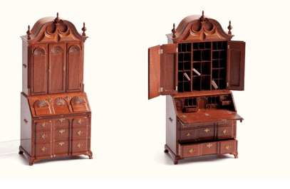
Miniature Woodworking with Kelli Risoli at September Meeting
By Ken Gregg
To really challenge your woodworking skills, consider this:
You have a simple chest with 4 drawers made of oak. It’s 48” tall, 36” wide, and 18” deep.
The drawers are dovetailed with turned knobs.
Supplies used when you made it:
4 - sets of 12" drawer slides
8 - knobs or handles (let's say they are turned are are 1-1/2” diameter and 1-1/2” long)
2 - 2x2x8 feet long
1 - 1x12x10 feet long
1 - 1/4" plywood - full sheet
3 - 1x3x8 feet long
3 - 1x2x8 feet long
3 - 1x6x8 feet long
1 - 1x8x12 feet long
3 inch screws
3/4 inch finish nails
1 1/4 inch finish nails
1-1/4" Pocket Hole Screws
Now scale it down to “dollhouse” size (1”=1’): That will be 4” tall, 3” wide and 1-1/2” deep.
Converting Real-Life material, this is what you’ll need:
Hardware:
Drawer slides - 1” long
Knobs - 3/32” diameter x 3/32” long
3” screws = 1/4”
3/4” finish nails = 1/16”
1-1/4” finish nails = 3/32”
1-1/4” Pocket Hole Screws = 3/32”
Stock:
2x2x8 = 7/32” x 7/32” x 8”
1x12x10 = 5/32” x 31/32” x 10”
1/4”x4’x8’ sheet = 1/32” x 4” x 8”
1x3x8 = 5/32” x 9/32” x 8”
1x2x8’ = 5/32” x 7/32” x 8”
1x6x8’ = 5/32” x 17/32” x 8”
1x8x12’ = 5/32” x 23/32” x 12”
Let’s stop right there. Where exactly are you going to find these supplies? Drawer slides? Probably going to have to use some sort of wooden slide. What size would it be?
Knobs? I’d probably use a dressmakers pin and paint it. Since the original chest used pocket screws, what kind of joint should be used instead? (Unless of course you happen to have on hand a Kreg Jig that’s appropriately sized.)
What wood would look the best? Something with lots of figure?
Many more examples and lots of information will be shared at the September meeting.
Salvaging “Bad Boards” at the August Guild Meeting
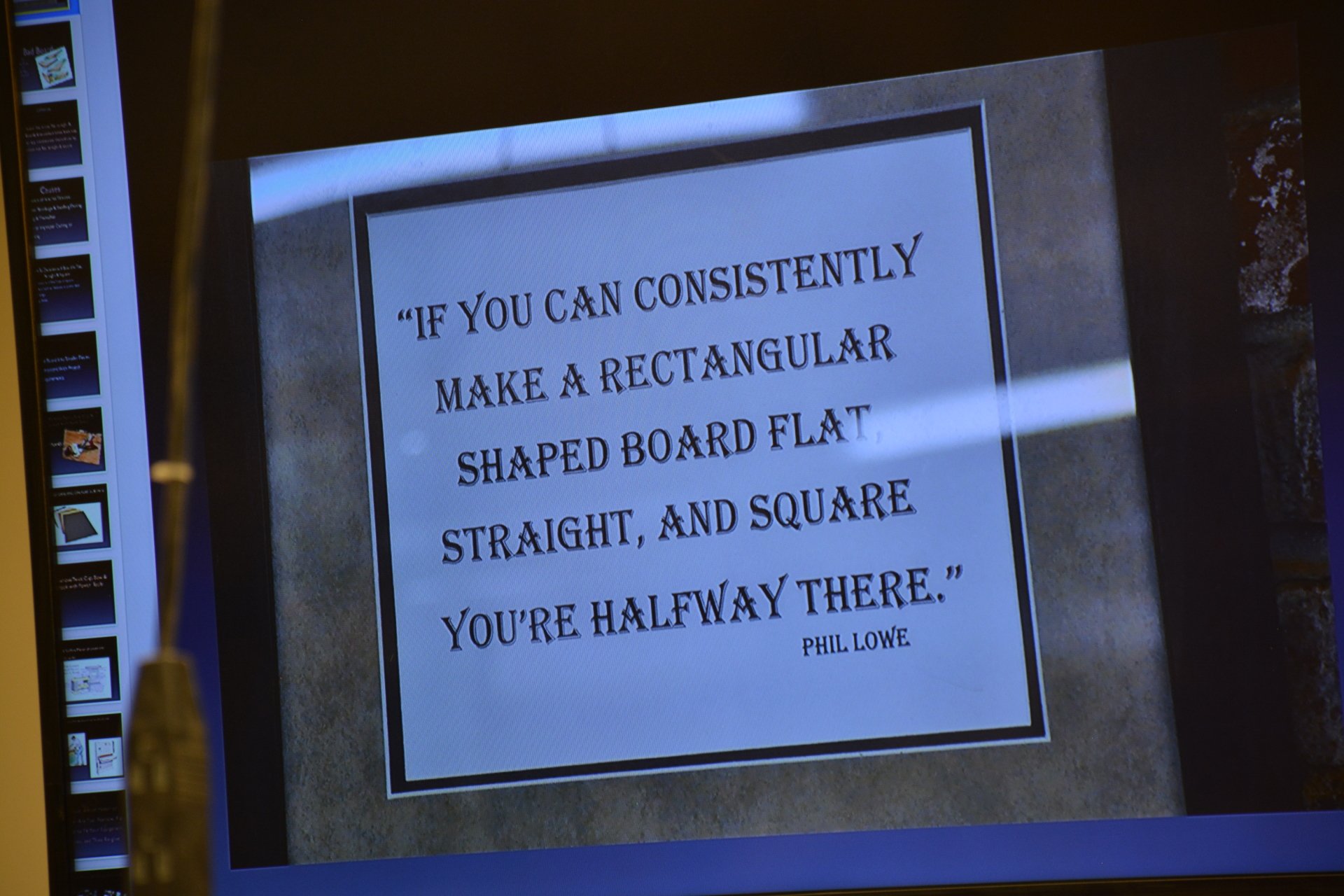
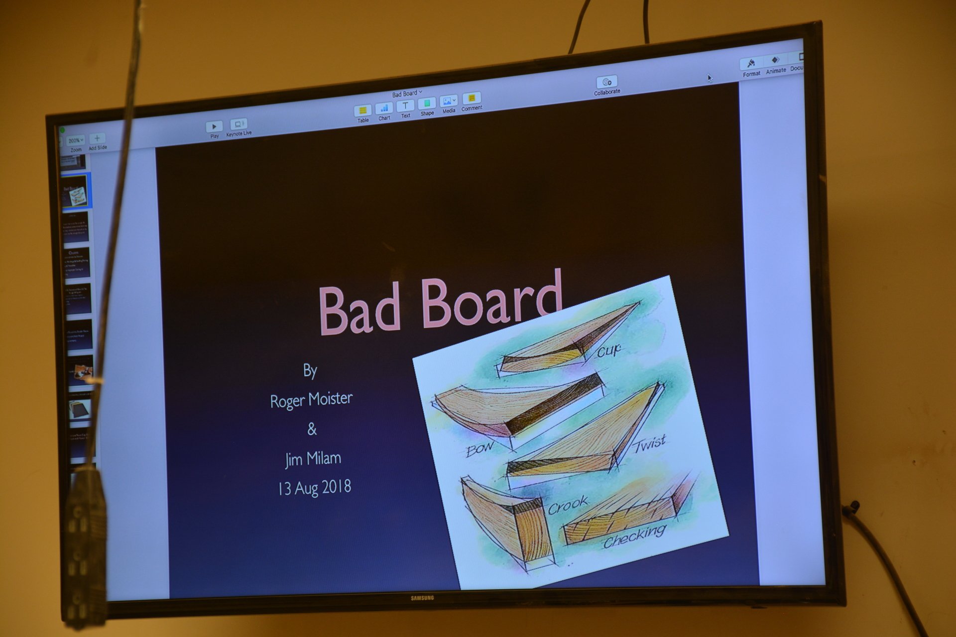
The universal tenet is that successful woodworking can only be accomplished when the corresponding sides and edges of a board are flat, parallel, and the corners square. Perfectly flat and square stock almost never comes from the lumber yard, and frequently the stock is so severely warped, twisted, cupped, or bowed that it qualifies as a Bad Board.
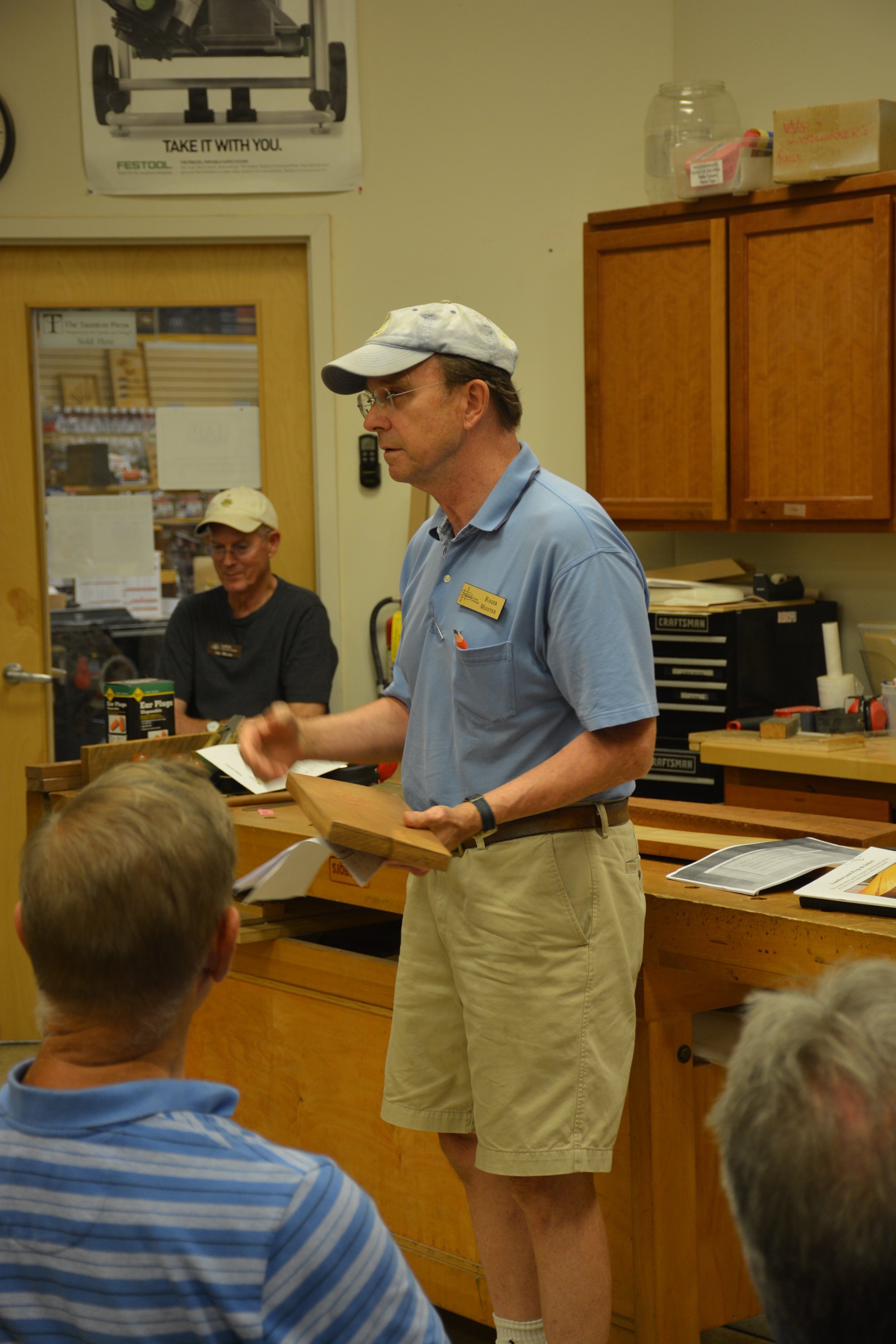
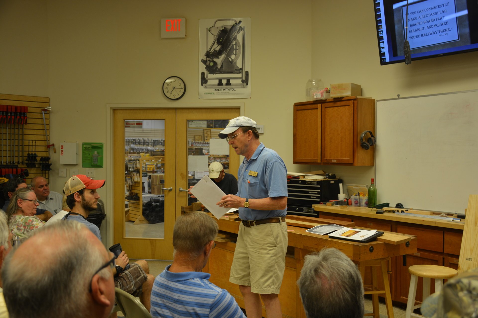
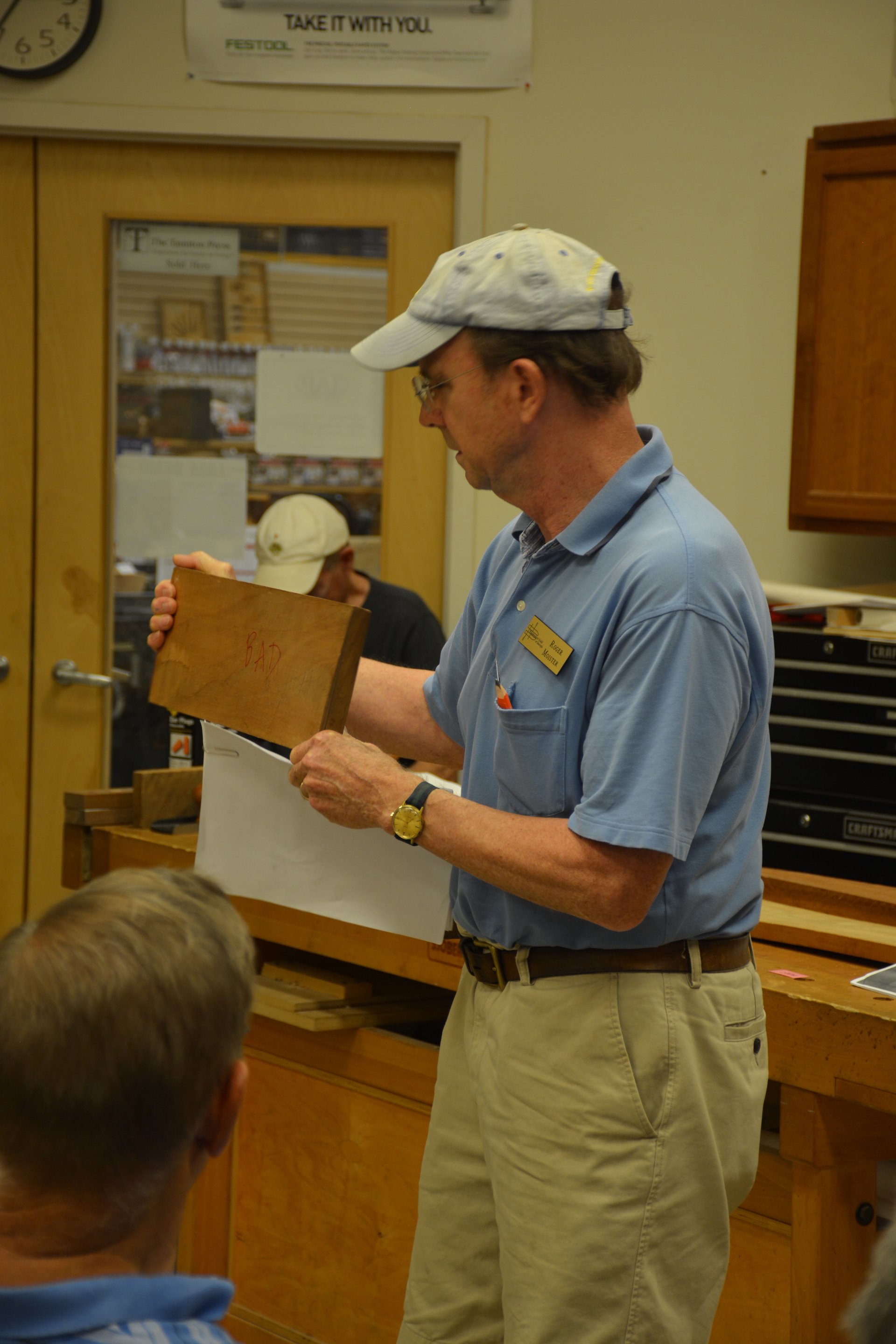
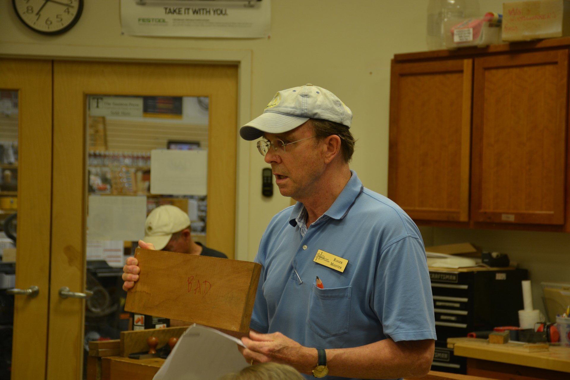
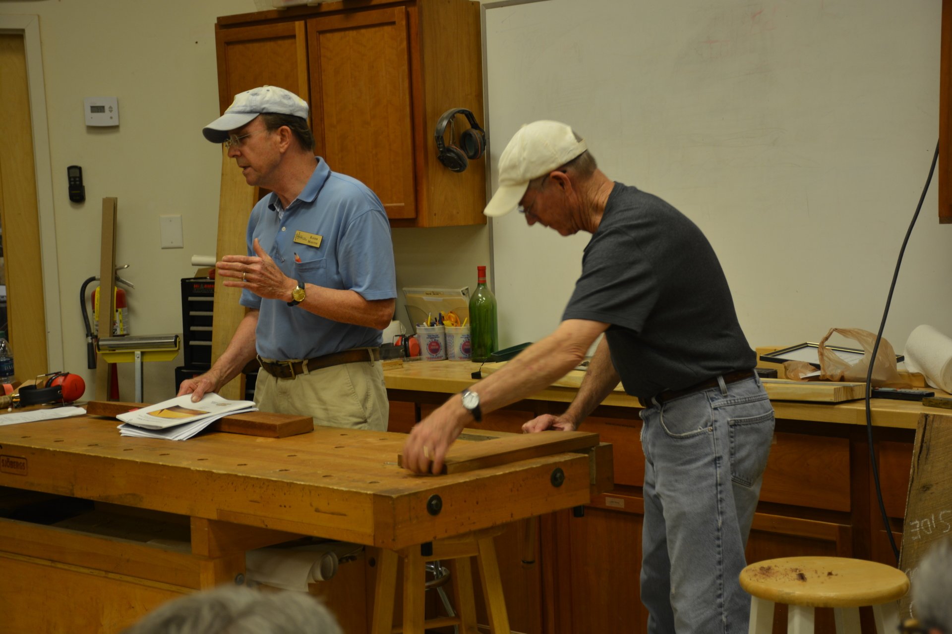
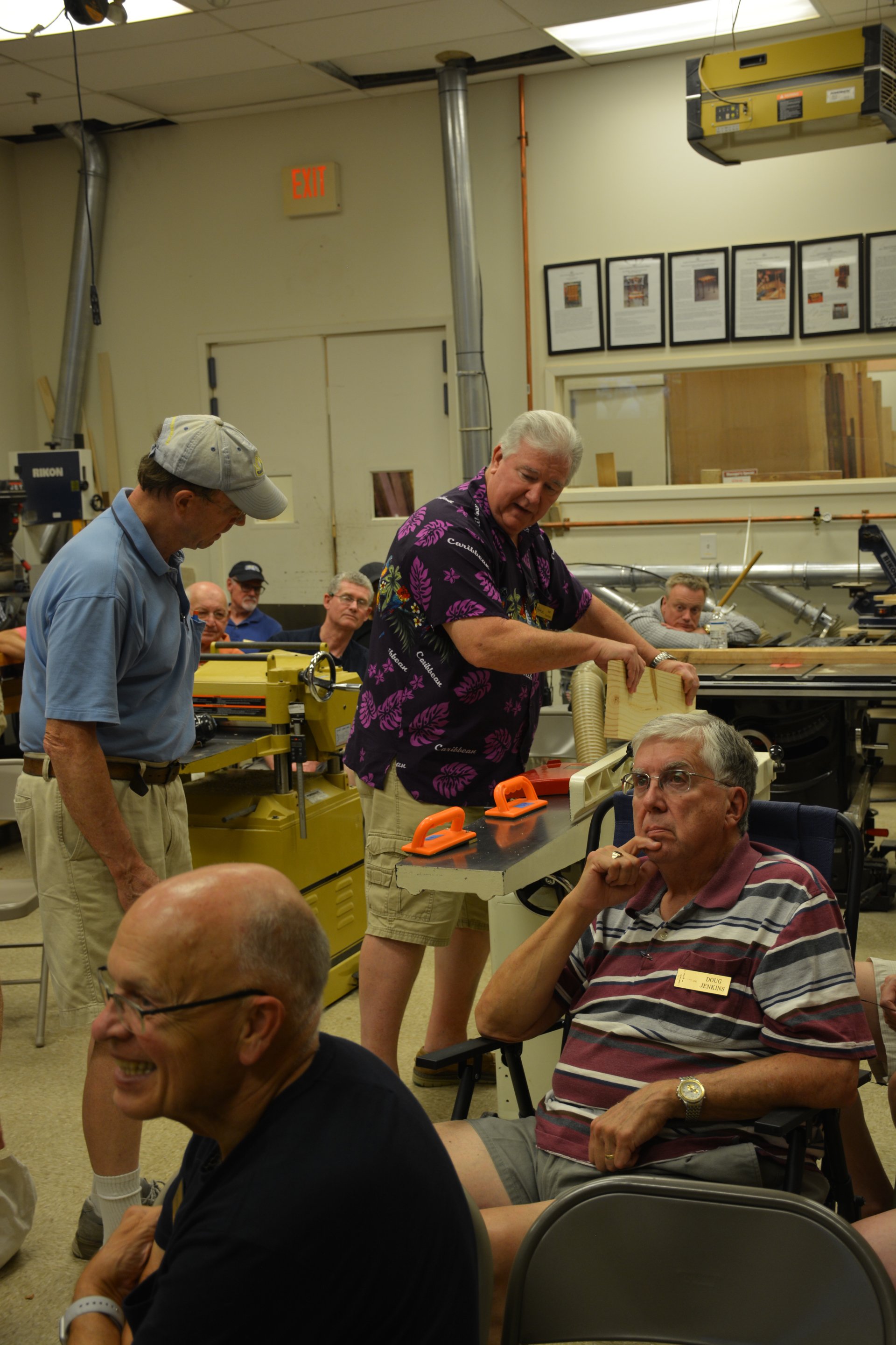
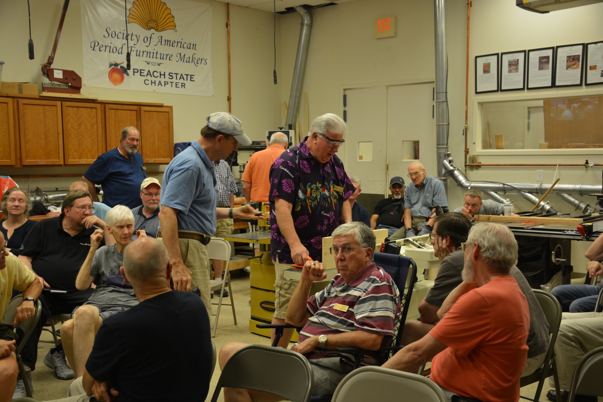
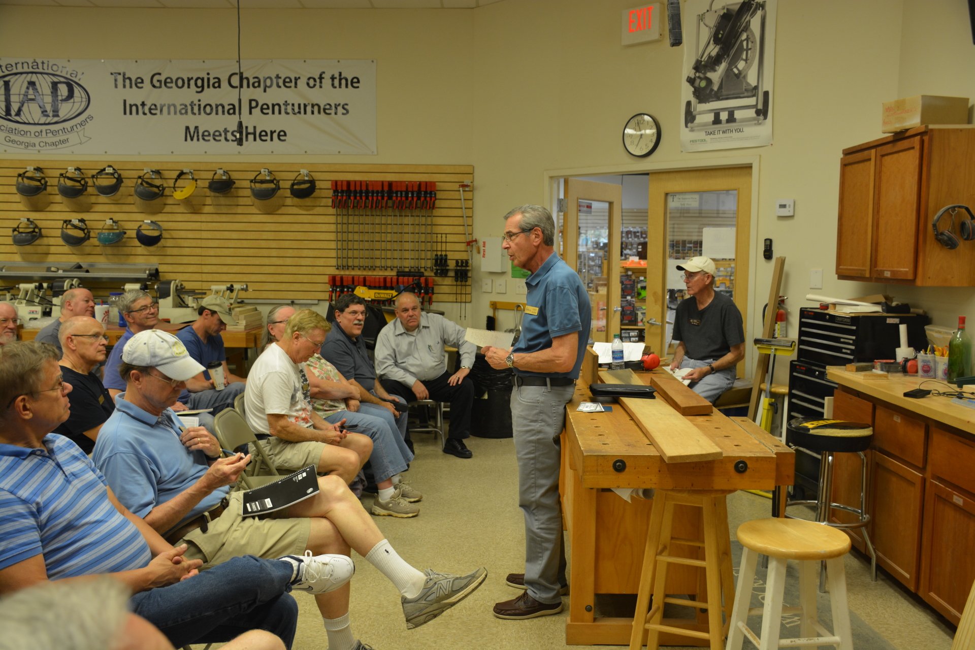
To salvage a Bad Board, rather than use it for firewood, the various tools and techniques in alleviating this problem were discussed and demonstrated by Roger Moister
and Jim Milam at the August Guild Meeting.
Roger introduced the concept of what a Bad Board is, and reviewed the different methods and tools required for making them useful for a project.
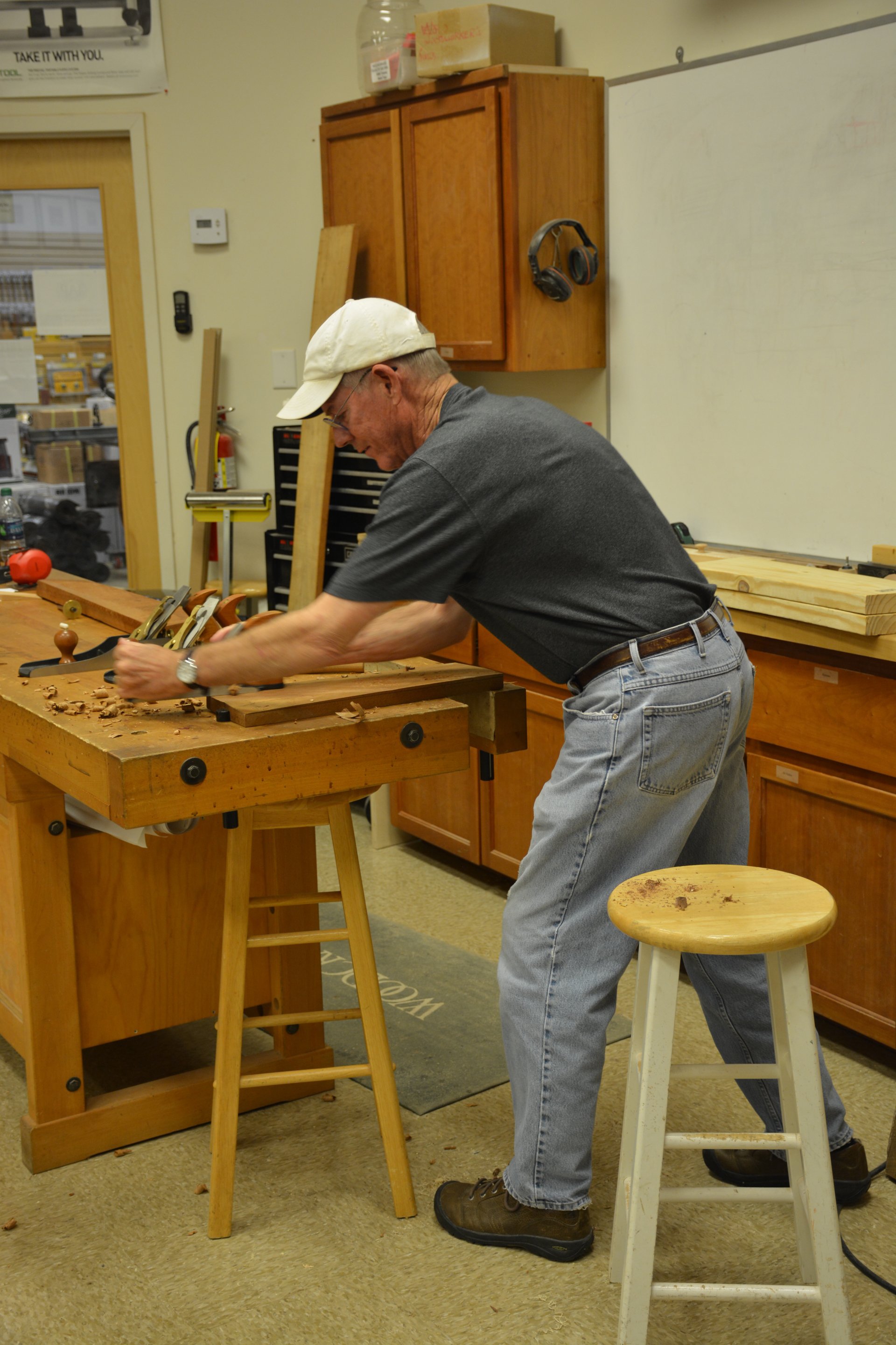
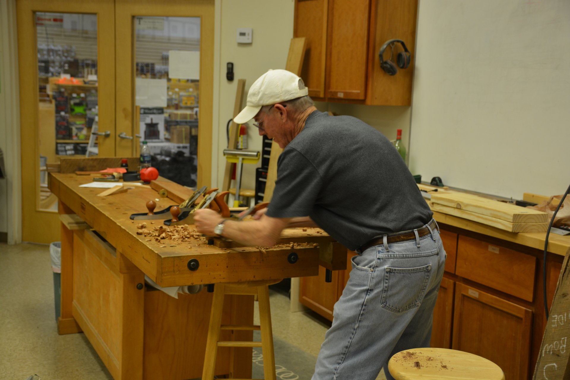
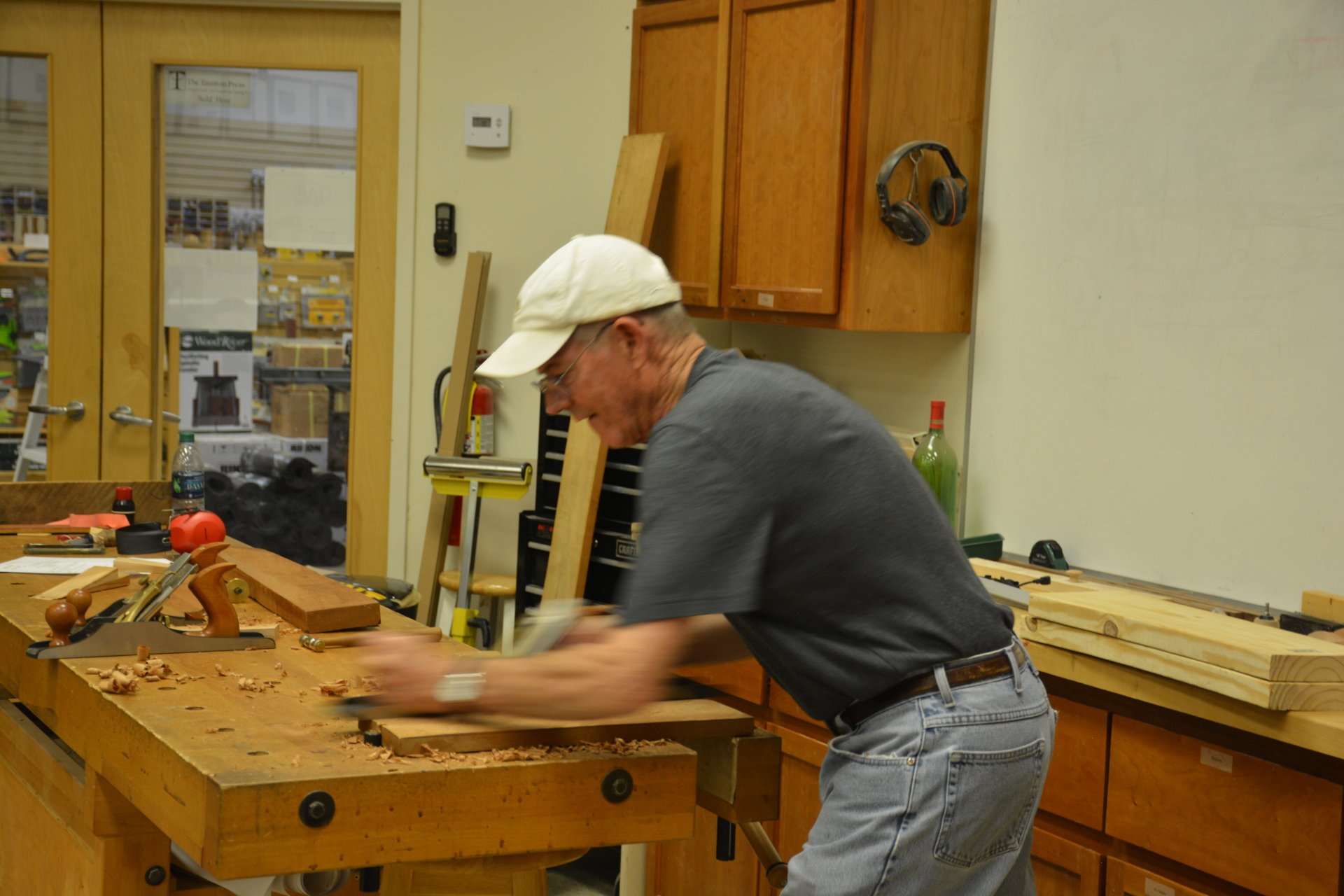
Jim then demonstrated using a hand plane to remove the high points from a board. Beginning with a #6 jack plane and going across the grain at a 30 - 45 degree angle to remove all of the high points, he then used a #7 jointer plane with the grain to obtain overall flatness. He also stated that he would rather hand planes than go to the gym - much more satisfying and equally good for the heart ! He also showed the use of winding sticks to help determine the progress toward flatness.
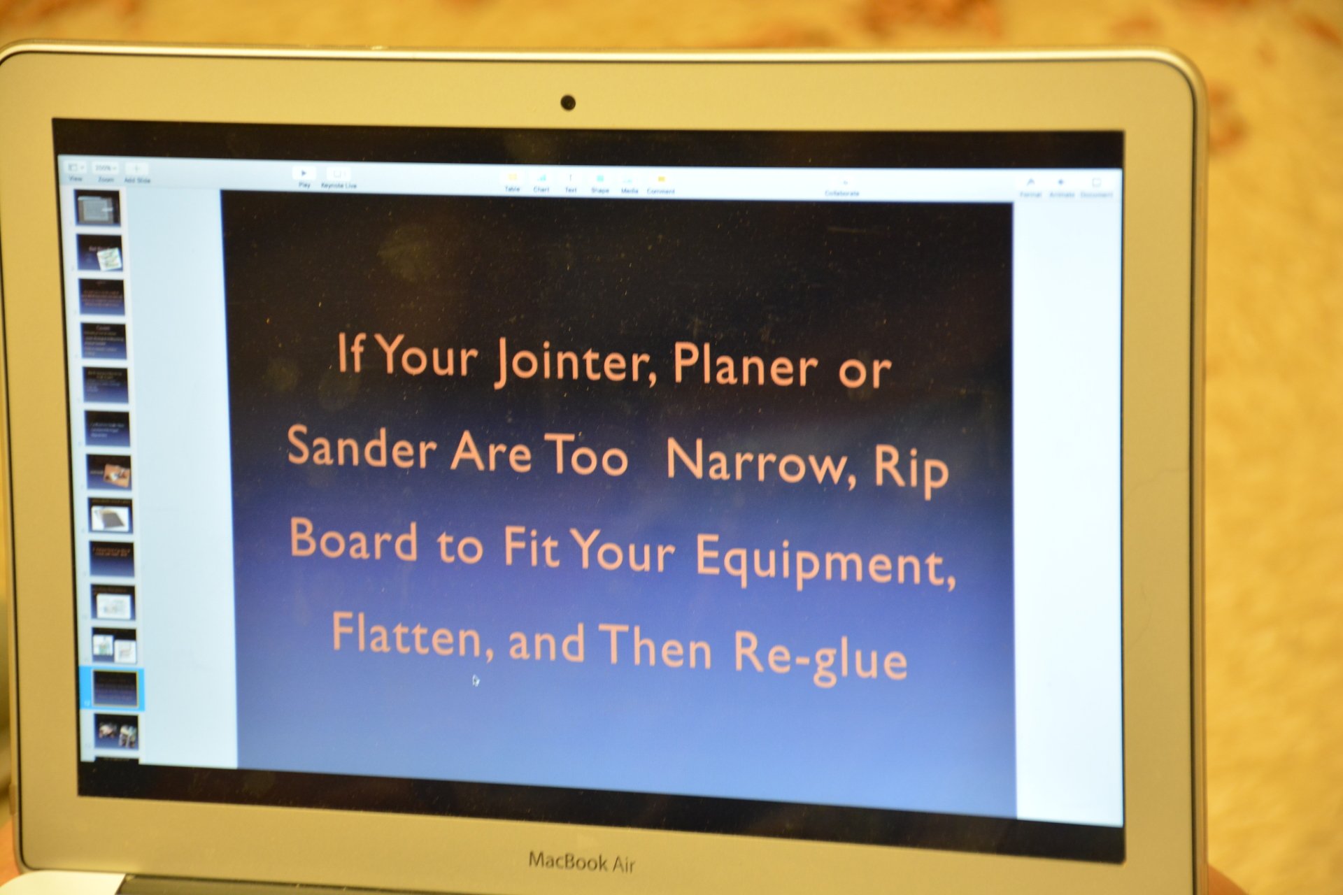
Roger then began the discussion and demonstration of flattening the first side on the jointer, then squaring up one of the edges (with the newly flattened face against the jointer's fence - which must be square to the bed). If the board's flaws are very extreme, or if it is too wide for the jointer, ripping it narrower, and possibly cutting it as short as possible based on your project's cut list, and then edge gluing later may be required. The next step is running it through the thickness planer to achieve two flat, parallel sides.
Also discussed, in the realm of power tools, was using a portable planer for "hogging" off high spots, as well as a hand held router with a sled.
A short video was also shown for a custom sled that gives a thickness planer the ability to flatten the first face, for those that do not have access to a jointer.
Many Thanks
to Jim
and Roger
and All involved for a great presentation on this all-important topic !
Following is a list of “Bad Board” resources they provided:
There are many other articles and videos on this subject in Fine Woodworking (FWW) and other places.
A Planer Sled For Milling Lumber by Keith Rust FWW #175 & video
How To Mill Lumber & Cut Parts To Size by Stuart Lipp FWW #213
How To Get Square, Stable Stock by Gary Rogowski FWW #165
How To Mill Lumber Safely by Michael Fortune FWW #196
Flatten Wide Boards On A Small Jointer by Mike Pekovich FWW video Aug 7, 2025






President’s Message - September 2018
Gary Fader
So, How Are We Doing?
In my first message back in February, I cited several areas of Guild administration that I felt needed attention. So, here again is the list of issues and current status:
• Our Board position descriptions are about 5 years old and many do not reflect current practices. This makes it difficult for a new Board member to know his job. To date, the Board has revised the 17 existing position descriptions, developed 1 new one, and approved 11 of these.
• Our membership is aging and declining. We need to reach out to a broad spectrum of potential members so our programs can continue and benefit others. Our current membership stands at approximately 140, including 28 new members that joined in 2018.
• Our community involvement, specially regarding charitable projects has not been an area of focus. Although somewhat addressed last year by making 100 toys for children in Scottish Rite Hospital and making tables for returning veterans, we could do much more and have a great time doing it. This year Nuane Neely is coordinating the preparation of 50 trucks and 60 puzzles, again for donation to Scottish Rite.
• Our scholarship program is hardly used, although it makes up a large portion of our annual budget. Things have improved in this area and we expect to exhaust our scholarship budget of $1500. I think the awards being raffled off from Highland Hardware have benefitted several members and increased the attention on taking courses.
• Our policy on Membership Privileges specifies that we have a mentoring program, but it’s not well defined or implemented. We now have a list of willing mentors that has been placed on the website. Now it’s up to us to take advantage of it.
• Our website has come a long way in development, but still could be better and more useful. Under the leadership of John Champion, a website development plan is underway. This will probably be a multi-year program and involve some cost, but expected to be well worth it.
In addition to the above, the membership approved a minor revision of our Bylaws, and the Board is reviewing the 11 Guild policies and has revised 2 of them to reflect current practices. Roger Moister has identified the location of all Guild assets so we can quickly find the things we need, and our treasurer, Art Sanders, has invested about half of our monetary reserves in 3 laddered CDs.
I’m please to report that we continue to get very good attendance at our monthly meetings and positive feedback on the programs being arranged by Ken Gregg and the Programs Committee.
That said, there are always opportunities for improvement, so keep the feedback and suggestions coming. Any Board member and I would welcome your input at any time, in any way.
Guild Charity Toy Making - 2018
Join Us September 13th
The Guild is again making toys for hospitalized children. They will be given to children during the Winter holidays. Several members are already cutting out puzzles. Parts for toy trains will be cut out at a special meeting on September 13, at 1:00 PM at Woodcraft. That afternoon, we will be cutting components, sanding parts, squaring up & gluing puzzles, and finally branding them with the Guild Logo.
We need and would certainly appreciate your participation!
Please E-mail Nuane Neely if you can help out at Woodcraft
on Thursday Sept. 13th at 1:00 PM
[email protected]
In October, our regular 2nd Monday meeting is usually cancelled because of the October Mini-Symposium, to be held at Suwanee Lumber Company on October 13. However, this year we will meet at Woodcraft at 7:00 PM on the second Monday, October 8, and will assemble the toys using the parts made on September 13. We had a great time and fellowship last year, and hope you will be able come and help with the final toys assembly this year!
Chippendale Chair Class on Guild Scholarship
By Roger Moister
Thank you to the Guild for granting me a scholarship for a class to build a Chippendale side chair. The class, held July 28 through Aug 3, 2025 at Woodcraft, was organized by the Peach State Chapter of the Society of the American Period Furniture Makers (SAPFM). I knew everyone in the class, so group chemistry was good as well as there being a tendency of participants to help each other. We worked nearly 54 hours to get the chair substantially completed. It was challenging and fun!
Our instructor was Ben Hobbs, a master furniture and chair maker, from Hertford (Perquimans County) North Carolina on the eastern shore. He teaches woodworking there and builds commission pieces. A former math teacher, Ben has built over 3000 pieces since 1982 and is a recipient of the Cartouche Award, the highest distinction from SAPFM. About the same age as class participants, Ben was very personable and an effective teacher, being patient and firm as he kept the class on task and moving to build a chair for each of the 8 participants.
Ben brought his patterns so we began by cutting out the back legs and then other parts later. Most of us traced patterns for our later personal use.
Generally, one thinks of a chair as having angles and curves, and being intimidating to build. Ben assured us at the beginning that it’s not that hard to build a chair, and once you build one, you can build most others. We embarked without a measured drawing, handout or known angles. Ben noted the seat of our chair was wider in the front than in the back to form a trapezoid and that the back legs were slanting inward on the sides from top to bottom.
Attaching the two back legs to the back seat rail and stretcher at the bottom was our first task. Ben drew a sketch with some dimensions and then showed us how to “pick up the angle” for the ends of the rear rail using a bevel square. So we got the angle we needed without knowing its degree. We cut the back rail and then the back stretcher, mortised the legs, cut the tenons, fitted the joint and glued up to produce the back of the chair.
All participants had already sawed out and sanded their splat and brought it to class to save
time. We fitted the splat into the shoe which we had previously shaped for gluing into the top of the back rail. With crest rail stock mortised to accept the splat, we fitted it and determined where to cut off the top of the back legs. Ben demonstrated this using a framing square as a flat bar and a clamp from its edge and the bottom of the back rail to draw the splat into place. We then cut out the decorative front of the crest rail and its curved profile and proceeded to glue up, which completed the back of the chair.
Shaping and sanding the backside of the rear legs followed. I found some of Ben’s tools interesting for this, and I had had limited experience using them. To fair the curve, we used a Stanley No. 113 adjustable circular sole plane as well as No. 49 and No. 50 rasps and then a Stanley No. 55 curved spokeshave to round the legs. Ben used a Stanley No. 80 cabinet scraper on flat surfaces which he usually had leveled or smoothed beforehand with a Veritas No. 4 1/2 hand plane. Hand planing, scraping and hand sanding, 220 grit with the grain was the usual regimen for finishing all surfaces. Peculiar to Ben, he preferred to mark lines with a ball-point pen because the line is uniformly thin, or knife it in with a boxcutter.
Recalling that the chair seat is a trapezoid leads to how the side rails attach the front and back legs and how this is laid out and built. Envision a side rail running from front to back of the chair at an angle and made of straight stock. Making the attachment requires either angling the mortises or the tenons since the seat is a trapezoid - being wider at the front than the back. We angled the tenons so they stuck out of the ends of the rails in opposing directions at the same angle. Ben demonstrated the layout with the bevel square. Once fitted into the front and back legs, the rail in effect was twisted so that the back end of the rail protruded past the side of the rear leg about 1/8 inch, and the front of the rail died into the outside corner of the front leg. The back end protrusion of the side rail was planed off flush with the side of back leg toward the front at a 45 degree downward angle to where the front of the side rail died into the front leg. Then the outside sliver of the front leg was planed off to create one smooth surface for the side rail. Honestly, how all this came together was quite ingenious and it has been going since Chippendale’s day, but probably not widely observed or known by many people, I believe.
To install the side stretchers below the seat, Ben picked up another angle from the inside of the back leg at floor level and then cut the stretchers to length, created the tenons and fitted them into the back leg mortises. Front legs joints were also fitted.
Fitting all joints to tight, exact perfection was the critical task and Ben demonstrated several techniques of how to analyze a joint and then remove wood which prevented the joint from closing. Clamps were used to pull the chair together. These were the monster old Jorgensen 2 inch steel I beam clamps with a T bar on the screw end as a handle. These were heavy, easier to operate than a Bessey clamp and produced more force. In the end, fitted joints got pulled together under terrific force.
With the front legs attached by the front rail and after a successful dry fit of the chair, glue up came next. According to Ben, this is the most stressful step in construction. He announced his regimen. Rule 0ne: take care of the bladder. Then have all parts and the clamps laid out orderly and nearby. “Butter” both sides of all mortises and tenons with a light coat of Titebond Original (red label) glue. Fit the joints, apply the clamps and work fast because the glue dries quickly. Thin strips were used as pads to protect chair surfaces from the clamps. If a joint was off and did not close, Ben demonstrated how to reposition a clamp and change its pressure. Then we checked the chair for square using a framing square by placing the short side against the back of the seat with the corner end of the square registered at outside corner of the chair. The long end of the square extended up to the inside of the front leg and needed to show a gap of 3/4 inches on each side of the seat at the front leg to validate squareness of the chair. Mine did.
As I describe what happened in the class and the process followed to build the chair, the complexity of building a chair is suggested. Participating in the process and seeing how it is done is really necessary. Ben told us earlier that an older man had shown him how to build a chair in 1982.
Even though we each worked hard to build our chairs, we did not complete them. We ran out of time, and Ben had to hustle at the end to demonstrate how to build the slip seat and upholster it and install the middle stretcher. Nevertheless, I did take an assembled chair home.
So what’s left for me to do? Plenty: build the slip seat and upholster it, cut off the front legs and bead around the seat and down the front legs, fit the center stretcher with a sliding dovetail joint, shape the crest rail and its ears and carve the shell on it, carve the ribbon weave in the splat and its volutes, level the chair to the floor and apply a finish. That’s a good bit of work.
If “advancing the art and understanding of fine woodworking” is the Guild’s mission, then I certainly had that experience from attending the SAPFM Chippendale side chair class.


Let's Promote The Woodworking Show
START PLANNING YOUR PROJECT ENTRY FOR THE WOODWORKING SHOW !
The Woodworking Show 2019 is set for March 15-17 at the Cobb Galleria. The Guild will have a booth and is planning again to have a judged contest of your projects in the Craftsman and Masters categories. Start thinking now about what you will have to enter. This makes our booth more entertaining for guests who visit with us and helps to attract new members to the Guild. You can get further details about the entry process on our website under Activities > Woodworking Show.
Shown below are some of the entries this past at the Show this past Spring.


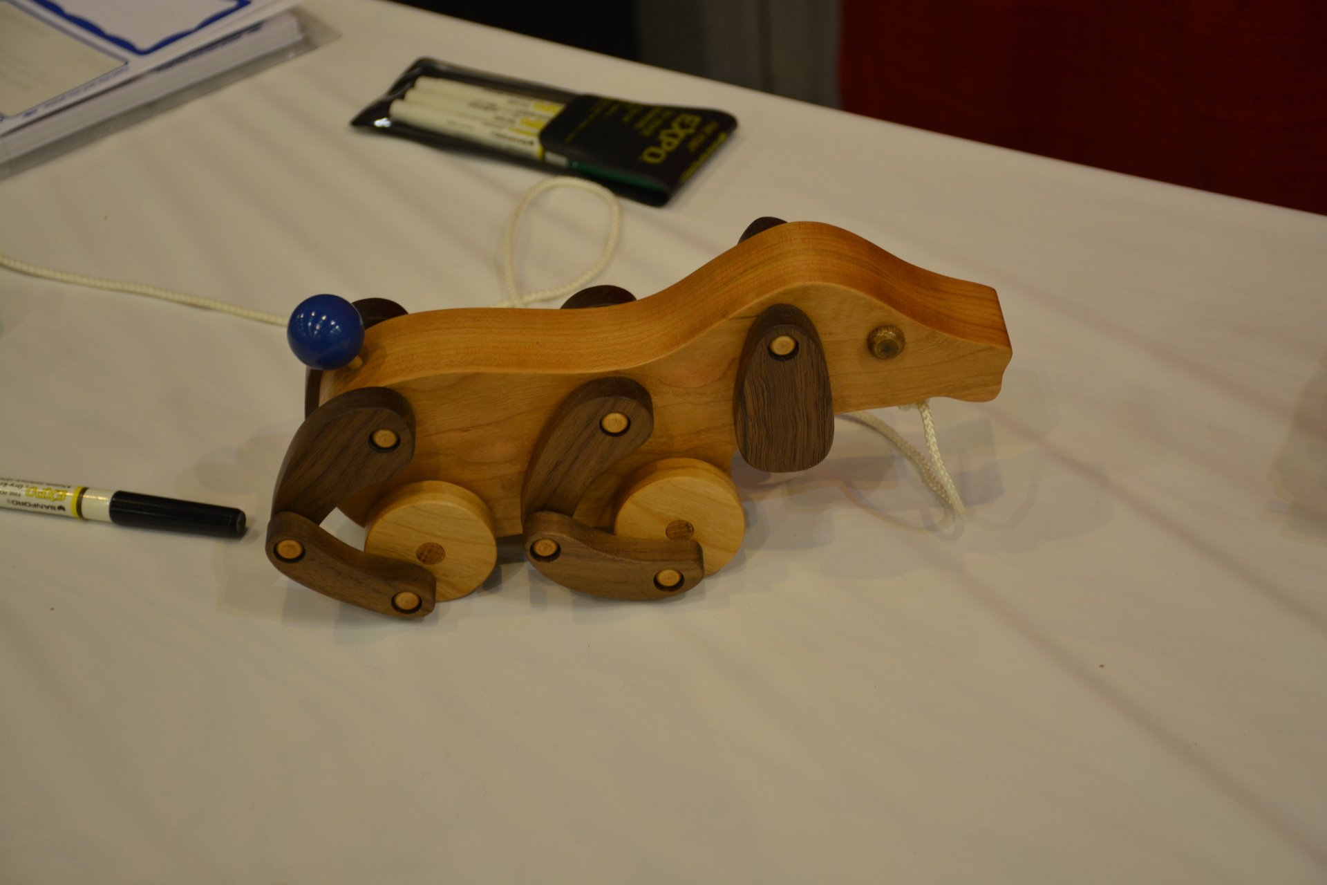

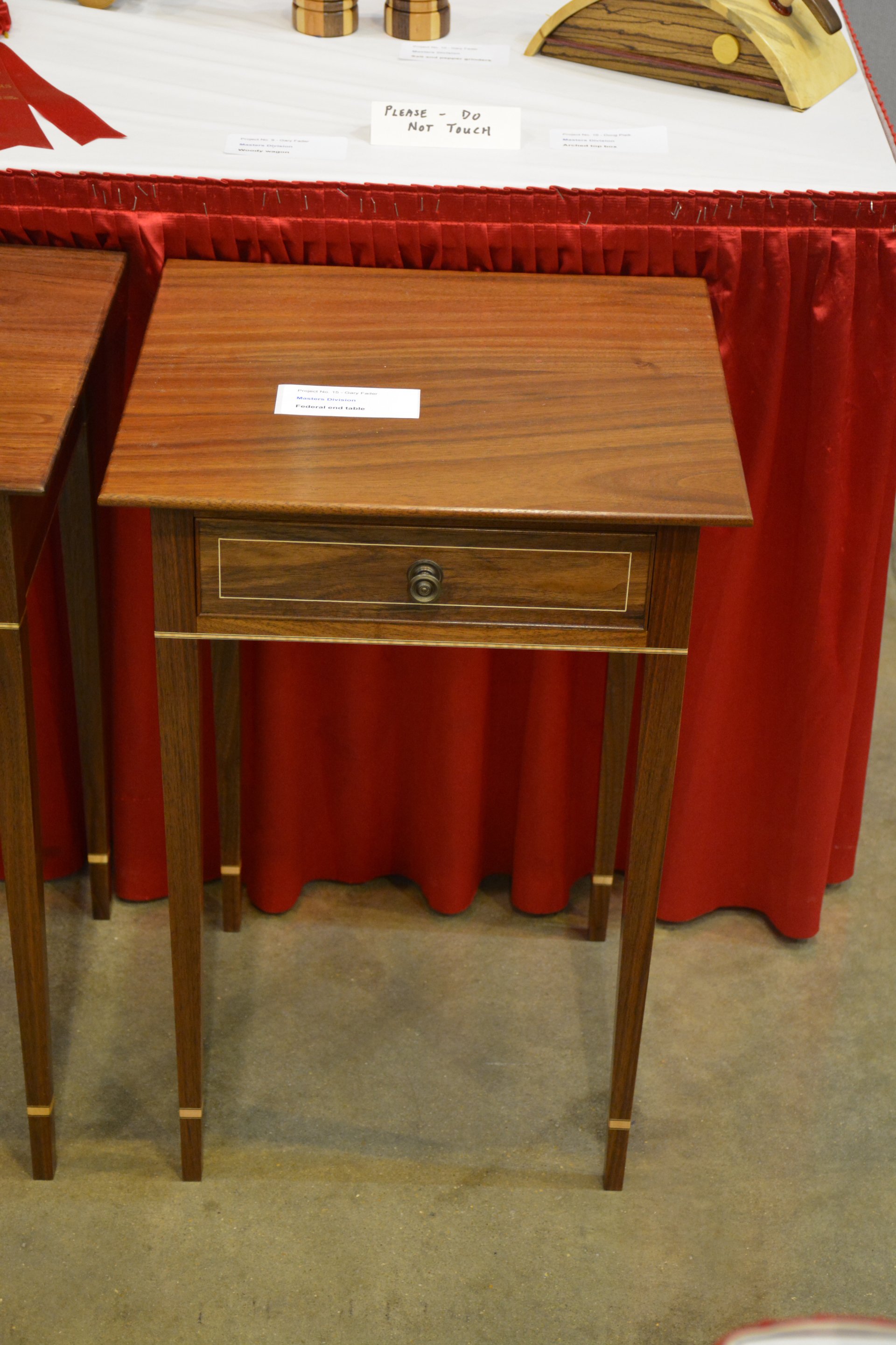
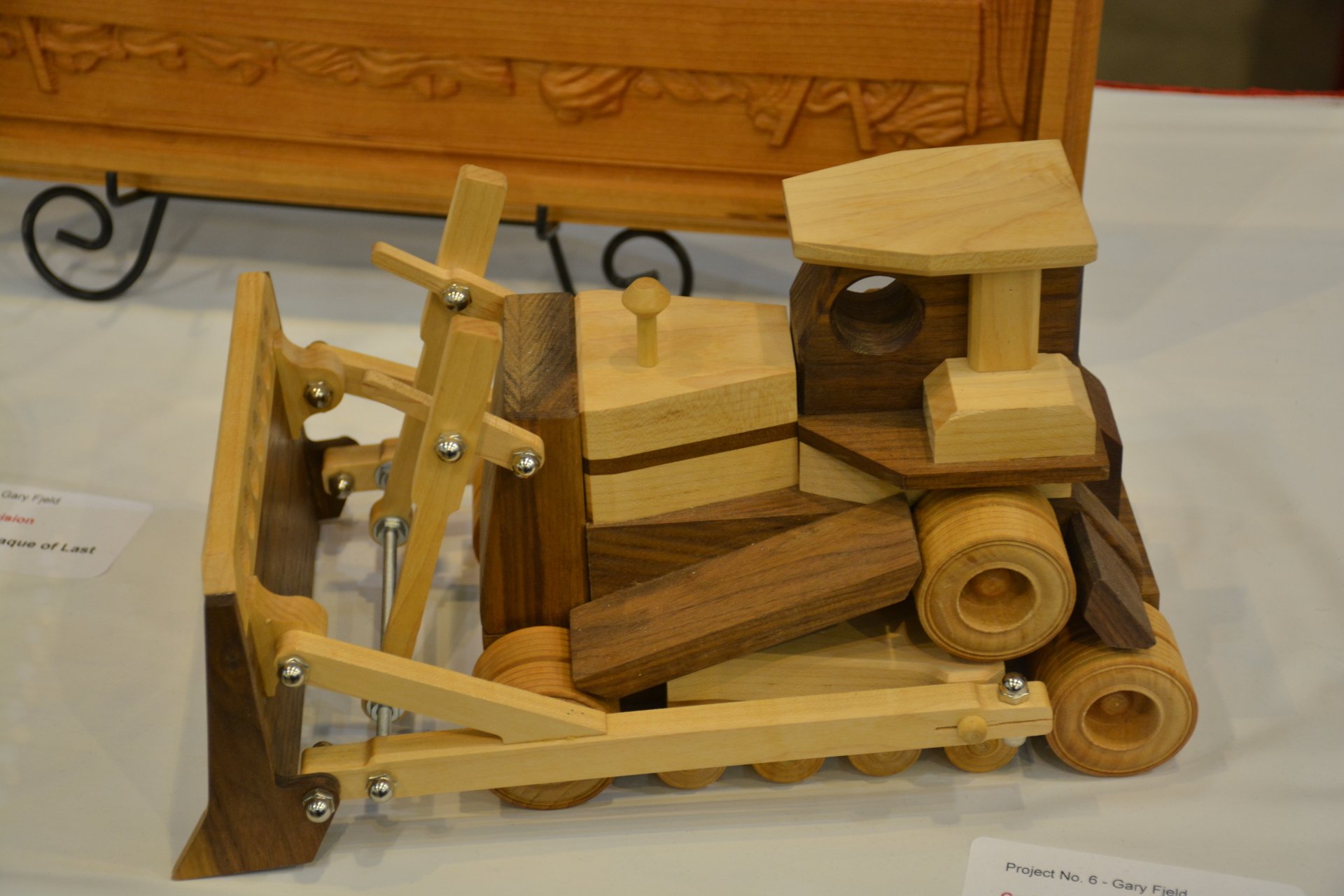
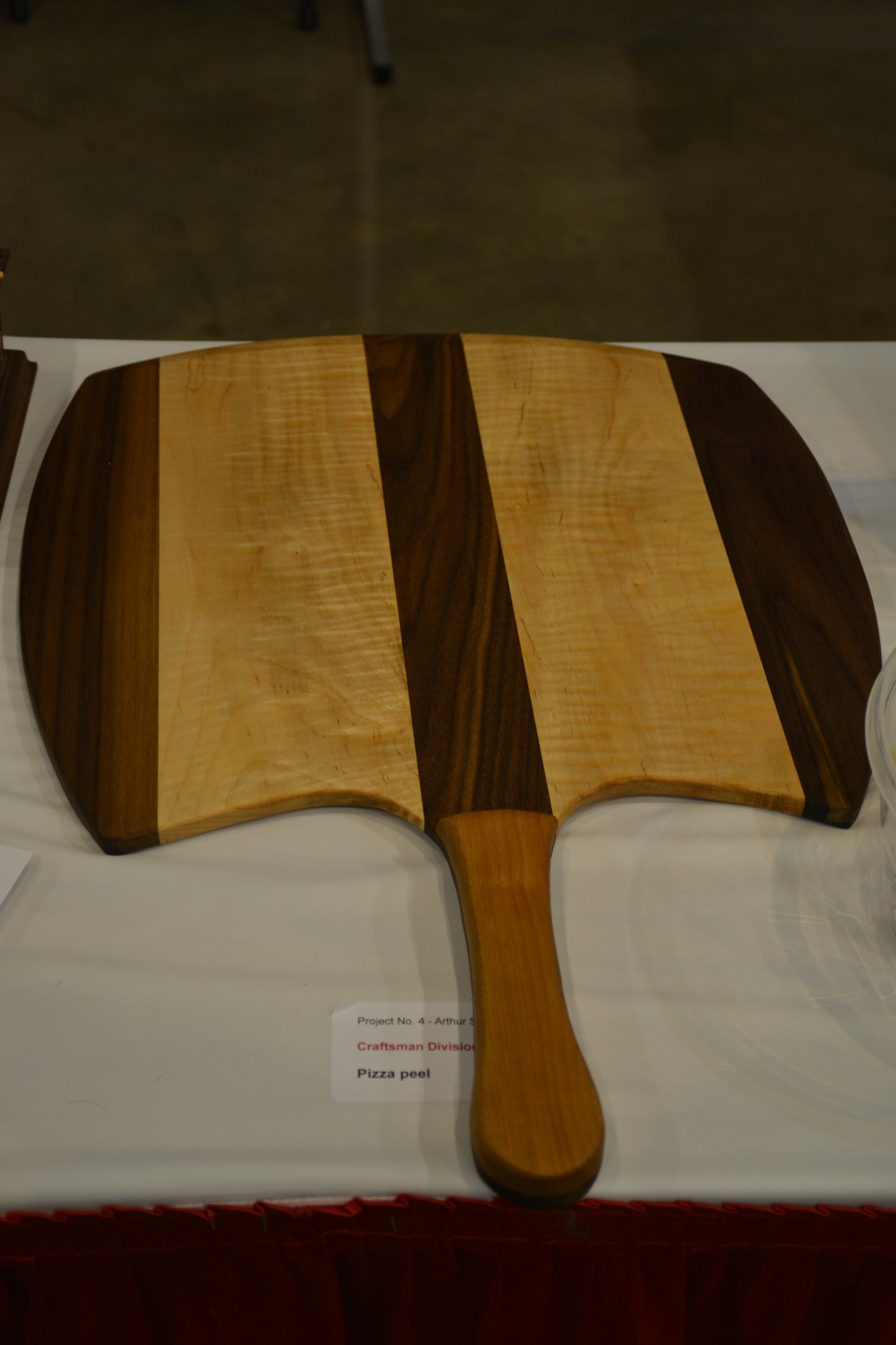
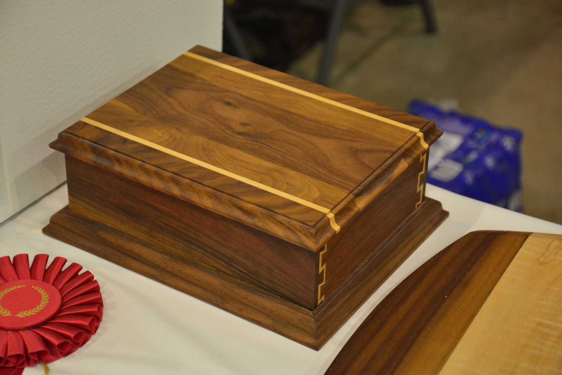


Show 'n Tell
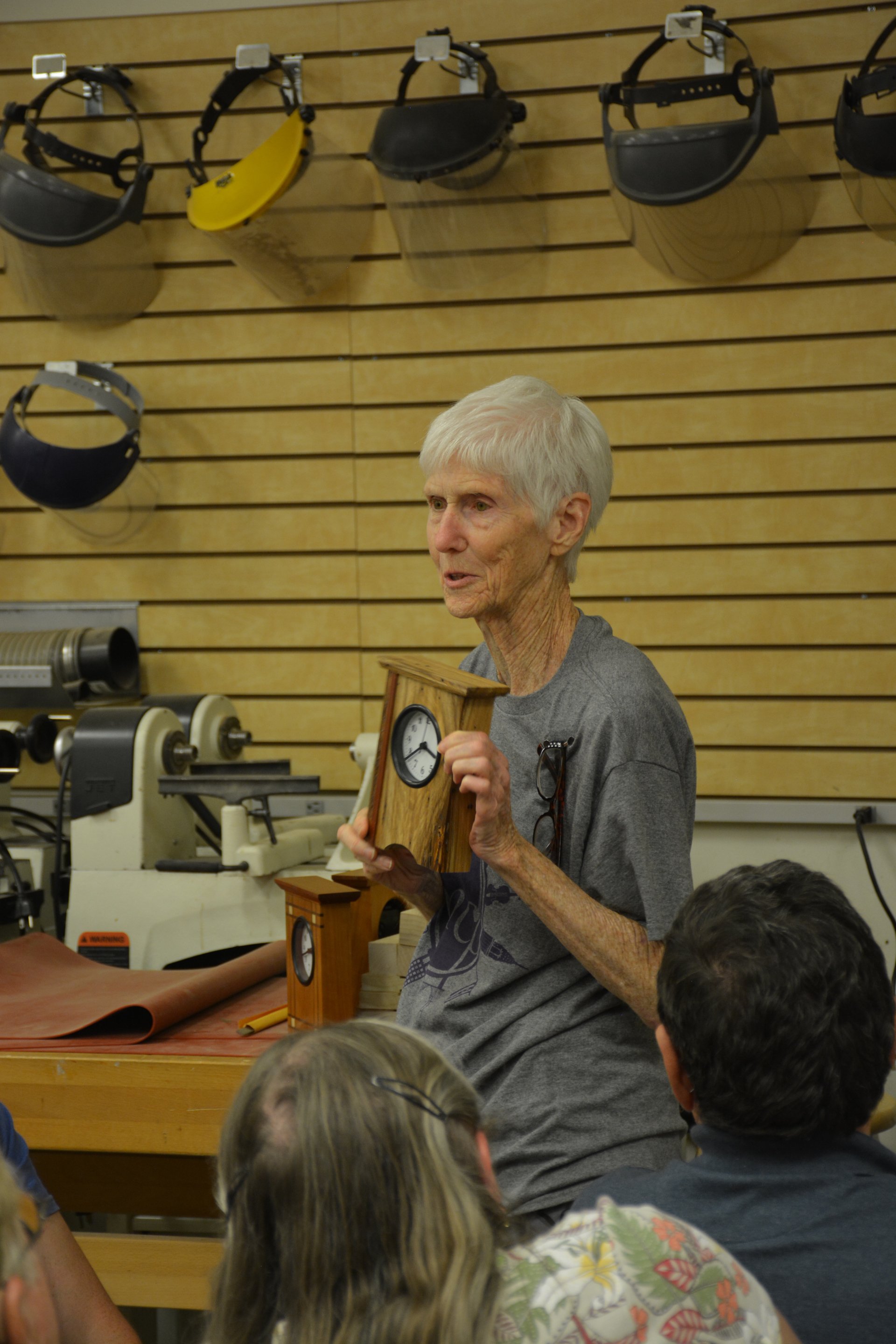
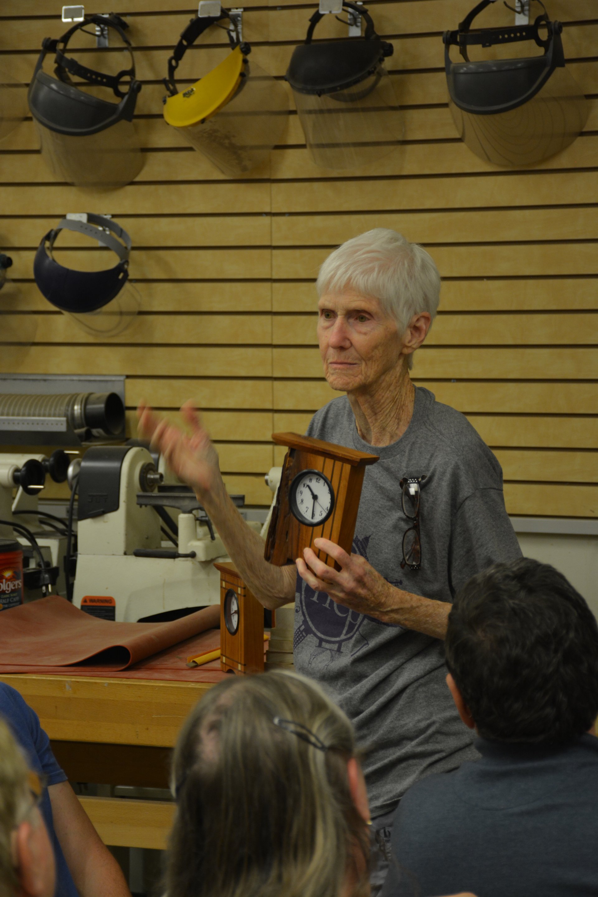
Guild member Nell Rodgers shared her skills at the August 13th Meeting at Woodcraft, showing her three clocks made predominantly with cherry with three distinct patterns / styles.
Beautiful clocks, Nell !
Bring Your Project(s) to Show 'N Tell
at the September 10th Meeting

Chris Bagby (right), owner of Highland Woodworking, receives their Patron Sponsor Plaque from Marc Spagnoulo (center) of The Wood Whisperer, at the direction of Tom Melcher, the Guild's Patron Sponsor Director.
Turners Group
PLEASE NOTE:
The "3rd Monday" Turners' Group at Rockler in Kennesaw will not meet this Summer, but possibly will resume.

Woodworkers Guild of Georgia
Upcoming Events
Monday, September 10
Monthly Meeting Woodcraft - Alpharetta 7:00 PM
Miniature Woodworking with Kelli Risoli
Thursday, September 13
Charity Toys Parts Fabrication Woodcraft - Alpharetta 1:00 PM
Monday, October 8
Charity Toys Assembly Woodcraft - Alpharetta 7:00 PM
Saturday, October 13
Fall Mini-Symposium Suwanee Lumber - 9:00 AM
Cabinet Making with Paul Fussel
Monday, November 12
Monthly Meeting Woodcraft - Alpharetta 7:00 PM
Creative Design in Woodworking with Doug Pisik
Free Demonstrations
Rockler 6690 Roswell Road / Sandy Springs
&
425 Ernest Barrett Pkwy / Kennesaw
Sept 8: 11:00 Worksharp WS3000 Power Sharpener
Sept 15: 11:00 Sriplox Knockdown Joinery System
Sept 22: 11:00 CarveWright CNC
Sept 29: 11:00 Rockler Sign Making Kit for Router
Oct. 6: 11:00 Pen Turning
Woodcraft 8560 Holcomb Bridge Road / Roswell
Sept 8: 1:00 Resawing and Blade Selection
Sept 15: 1:00 T-Tracks: Creating Jigs & Fixtures
Sept 22: 1:00 Sharpening Turning Gouges on the Tormek
Sept 29: 1:00 Using Stains: Water Vs Oil
Oct. 6: 1:00 Pen Turning
Trading Post - Buy and Sell
The Guild Website contains an interactive area for Guild members to place adds to Sell their woodworking related items, or Buy items that have been posted by others.
Trading Post - Buy and Sell is located on Message Board on the Resources Dropdown.
Click on http://wwgofga.com/forum/trading-post.html to go directly to the Trading Post
The Guild Board of Directors
Gary Fader President 770-977-7271
Art Sanders Treasurer 678-472-9117
Nuane Neely Community/Charitable Projects 770-922-1933
John Champion Woodworking Show 2018 404-307-0817
Tom Melcher Patron Sponsors 770-851-1098
Jim Milam Spring Symposium 2018 404-255-2314
Tom Risoli Website Administrator I 678-513-0887
Steven Sheppard Website Administrator II 770-316-7160
John Jones Vice-President, Secretary 678-576-7265
Jim Milam Member at Large 404-255-2314
Roger Moister Librarian 404-355-5033
Ken Kraft Membership 262-894-1725
Joe Rodriguez Scholarships 224-659-2225
Mark Haugland Newsletter 678-294-8043
Jim Wright Audio Visual/Member at Large 770-973-4692
John Jones Communications 678-576-7265
Ken Gregg Program Committee Chairman 678-799-6157
Support Your Woodworkers Guild of Georgia Patron Sponsors
Proof of Guild membership is required by
Patron Sponsors
that offer discounts. Your membership card can be printed from our Guild website. Login and go to Guild Info > Members Only, and click on Membership Card. If you would like to pick up your membership card at the next Guild meeting, email us
with your member name.
CAG Lumber - CAG Lumber is known for the largest selection of live edge slabs and unusual woods from all over the world.
We sell on the net, not the gross, so you take home what you pay for with no added on or hidden fees. We can saw your logs, kiln dry, resaw lumber, plane, straight line, and glue up ready. We are large enough to handle your needs and small enough to give one on one personal service. Guild members show membership card to receive 10% off most items, except items on clearance or discounted. Check out our web site, we stock a lot more than is listed. Website
Fintech Abrasives - For over 25 years, Fintech Technologies has been fabricating belts, sheets, rolls and other abrasives. They also have extensive experience with the application of the newest materials in coated abrasives. Family owned and operated in Belding, MI, Fintech is a highly respected company that takes pride in its excellent product quality, unmatched customer service, and superior technical support. Guild members are welcome to order products, as well as contact them with questions. Call them at 1-888-223-8768.Website
Highland Woodworking - Providing fine woodworking tools and project supplies since 1978, Highland defines itself as a learning community. The store has attracted nationally known teachers and authors including Tage Frid, Sam Maloof, Michael Dunbar, Rude Osolnik, Toshio Odate, Dale Nish, Mark Duginske and many others in Highland’s ongoing program of seminars and workshops. We have some great woodworking class opportunities coming up at Highland Woodworking! We have classes and seminars every week that include basic sharpening techniques, turning, finishing, project builds, and much more! Click to see our class schedule.
Their catalog of fine woodworking tools and workshops is available online, or visit its fully-stocked store at 1045 N. Highland Avenue in Atlanta, 30306. 404-872-4466. Website
Peach State Lumber Products - We are dealers of high grade/cabinet quality hardwoods, plywood, softwood, veneer and also carry a full line of cabinet grade plywood and turning blocks. We welcome small quantity orders and have a retail sales area open to the public. We also carry Hettich brand hinges and drawer slides. We have hardware screws and pocket hole screws. We now have live edge slabs in multiple species, great for bar tops, mantels, etc. Show your Guild membership card to receive their 500 b.f. price on any qualifying purchase.
Located at 4000 Moon Station Road, Kennesaw, 30144. 770-428-3622. Website
Peachtree Woodworking Supply -
Peachtree is a producer and retailer of high quality woodworking products with a goal of providing the woodworker with the hard to find tools and accessories. They stock over 6,000 different woodworking items. Those items include a wide selection of abrasives, books, DVD’s, clamps, router bits, glue, t-track, dust collection, and much more. Peachtree also carries the major brands. The store is located at 6684 Jimmy Carter Blvd., Suite 100, Norcross, GA 30071, 770-458-5539. Store Hours: Mon – Fri 9 am.- 5 p.m., Sat 9 am - 3 pm. Website
Redmond Machinery - Specializes in new and used woodworking and metal working machinery in a 25,000 square foot showroom. We stock machinery, accessories, and supplies from top-name manufacturers. Bargain hunters, check out our large inventory of used and scratch and dent machinery and accessories. We are a source for older American made Powermatic and Delta parts. We invite Guild members to stop by to visit us. We are located at 58 Weldon Rd., Palmetto, GA 30268, 770-683-7297 or 800-428-9898 Website
Rockler Woodworking and Hardware
- (Two Locations) - Rockler began as a mail order woodworking supply company and today the retail chain stretches across the United States. Our magazine, Woodworker’s Journal, is dedicated to offering plans, techniques, product reviews and tips to woodworkers. Our goal is to be your go-to woodworking resource. Please mention you are a Guild members BEFORE your purchase to receive 10% OFF everyday (normal exclusions apply).
We invite you to visit us at 6690 Roswell Road in Sandy Springs 404-460-1000, OR 425 Ernest W. Barrett Pkwy in Kennesaw 678-383-0087. Hours are Monday-Friday 9 am to 7 pm, Saturday 9 am to 6 pm, and Sunday 11 am to 4 pm. On Saturdays we have free demos. Website
Suwanee Lumber Company – Is a specialty hardwood supplier for custom cabinet and furniture makers as well as the general public. Suwanee features hardwood lumber with matching plywood and other materials to make every project a work of art. Please show your Guild membership card when shopping to receive Level 4 pricing (1,000 b.f. pricing).
Their location is 540 Satellite Blvd. in Suwanee, GA 30024. 770-945-2102. Website
Woodcraft - (Two Locations) – Has been a woodworker's favorite source for quality hand and power tools, equipment and supplies (including wood). Cabinet makers, wood turners, carvers and woodworkers in general rely on our friendly, experienced staff that is always available to help with the selection of tools and supplies as well as provide helpful advice on individual projects. We have fully equipped classroom facilities. Guild members receive 10% OFF qualifying purchases during our monthly Guild meeting or Symposiums at the Alpharetta store.
Stop by our store at 8560 Holcomb Bridge Road in Alpharetta, GA 30022, 770-587-3372 OR our West side Store at 351 Thornton Road in Lithia Springs. GA 30122, 770-485-5636. Website
The Woodworkers Guild of Georgia
Newsletter is published monthly, and is provided to all Guild members.
The Newsletter, and its archived copies, is posted on our website.
It is also available 24/7 on our Newsletter URL wwgga.tlehs.com
If you have questions, wish to contribute an article, etc., please use Feedback form below
The Guild welcomes everyone interested in fine woodworking to join. Annual membership dues are $45.00,
which can be paid at the monthly meeting (2nd Mondays) or mailed to:
Woodworkers Guild of Georgia / P.O. Box 1323 / Woodstock, GA 30188
You may also pay dues using PayPal at wwgofga.com
Enjoy Your Newsletter. We Welcome Your Feedback.